Mohamed Essam Ramzy

Architectural Consultant  •  Lead Design Architect  •  RIBA Part 01

Architecture, Technical Assurance & Construction Delivery.

RIBA Part 01 & SCE-Accredited Architectural Consultant with 8+ years of documented experience across Saudi Arabia and Egypt—combining architectural design, 2D AutoCAD technical execution packages, and 3D visualization with authoritative on-site construction supervision and handover.

0+
Years Experience (KSA & Egypt)
0+ m²
Supervised Development Area
0
Residential Units Handed Over
RIBA & SCE
RIBA Part 01 • SCE Accredited
00  /  Executive Profile

Site authority, not just site presence.

Combining RIBA Part 01 architectural design foundations, master 2D AutoCAD working drawing packages, and luxury exterior/interior visualization with contractor-facing consultancy and delivery-stage review.

Leading architectural inspections, shop-drawing and material submittals, formal approvals/rejections (Code A/B/C), corrective-action follow-up, snagging, municipality observations, and final handover across commercial, residential, and public-realm developments.

01. Construction Assurance

Full technical supervision from blockwork to final punch list. Façade systems, GRC screens, glazing, waterproofing, shop-drawing revise/resubmit cycles, and quality assurance.

02. Design Creation & 2D CAD

Master orthographic working elevations, 1:20 mechanical stone cladding sections, radial CNC setting-out templates, and natural stone execution packages.

03. Project Management

Weekly progress reporting, contractor interface, payment administration, municipality compliance, and documented close-out procedures.

04. 3D Visualization & Landscape

Photorealistic exterior & interior visualizations, environmental architecture canopies, sacred monuments, and luxury villa landscape architecture.

Licenses & International Accreditations

RIBA

Royal Institute of British Architects Part 01

Verified

RIBA  •  Issued Jun 2017

Credential ID: Membership No. 20036427

◇ Architectural Design, Architecture & Environmental Design Standards

SC الهيئة السعودية للمهندسين SAUDI COUNCIL OF ENGINEERS

Saudi Council of Engineers (SCE)

Verified

Professional Accreditation: Engineer  •  Issued Apr 2024 – Valid to Apr 2027

Credential ID: Membership No. 1026461

◇ Specialization: Environmental Architecture • KSA

Core Competencies & Tools: Shop-Drawing Review (Code A/B/C) Façade & GRC QA/QC Snagging & Handover AutoCAD 2D Execution Revit / BIM 3ds Max • V-Ray / Corona

01  /  Selected Consultancy & Built Work • Saudi Arabia

Built Work

Al Khobar, Saudi Arabia  |  Commercial • Residential • F&B

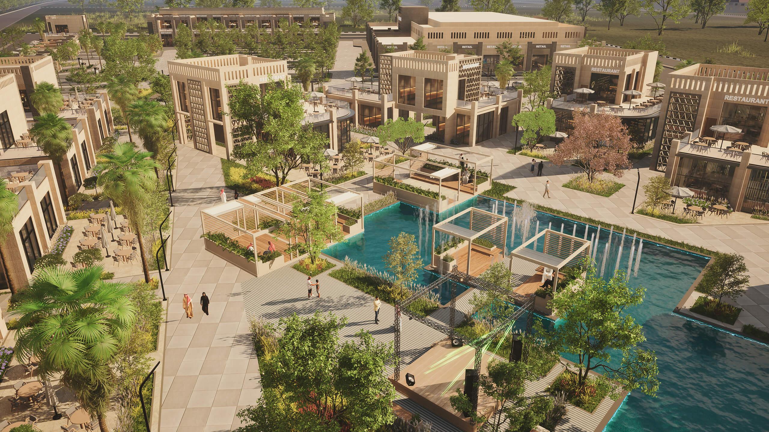
Hayat Walk — Commercial + Public Realm, Al Khobar
01 / Selected Project • Phase 2 Ongoing

Commercial + Public Realm • Al Khobar, KSA

HAYAT WALK

Role: Sole On-Site Architectural Consultant

A major two-phase development combining stone-clad retail buildings, pedestrian networks, outdoor gathering areas, and landscape. Lead architectural site review and contractor interface.

60,000 m²
Land Area
28,000 m²
Leasable Area
128
Retail Units

Scope: Architectural inspections & compliance across façade systems, GRC screens, steel canopy framework, glazing, waterproofing, and external works.

Technical Highlight: GRC screen at Building E-7 documented inspection, Code B "Approved as Noted," and corrective finishing execution.

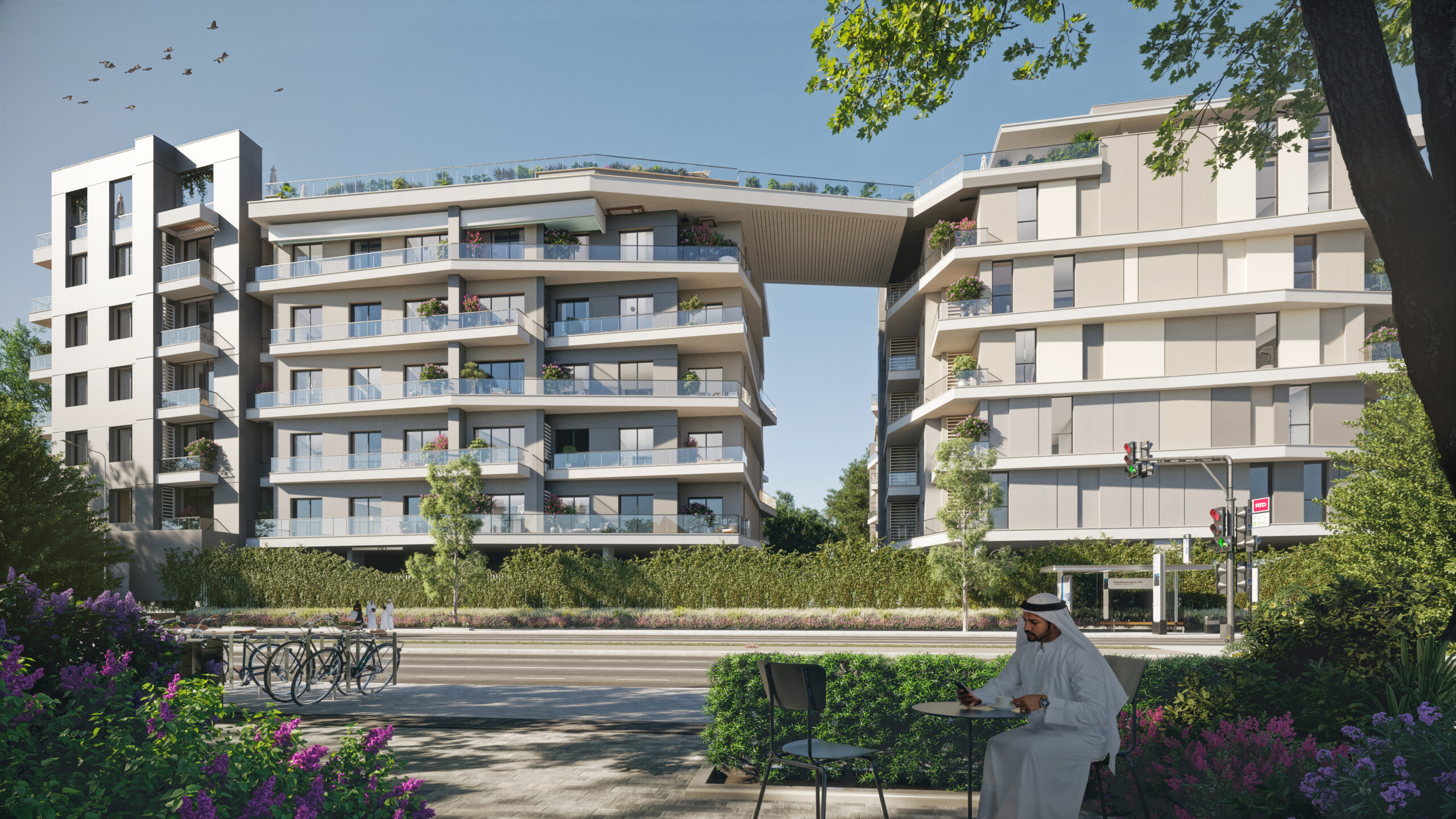
Residential Compound • Al Khobar, KSA

SAKAYA RESIDENCES

Role: Responsible On-Site Architectural Consultant

A five-building residential development (Rikaz) featuring private parking, apartment residences, rooftop penthouses, and shared amenities. Completed and handed over with full finishing inspection across all 165 apartments.

5
Buildings
165
Apartments
37,000 m²
Project Area

Technical Delivery: From blockwork to final punch list—drawing review, material inspections, finishing approval, and defect close-out.

Quality Control: 165-unit architectural finish inspections, shop-drawing revise/resubmit cycles, formal work rejection when required, and verified snagging.

Sakaya Residences — 165-Unit Compound, Al Khobar
02 / Selected Project • Handed Over
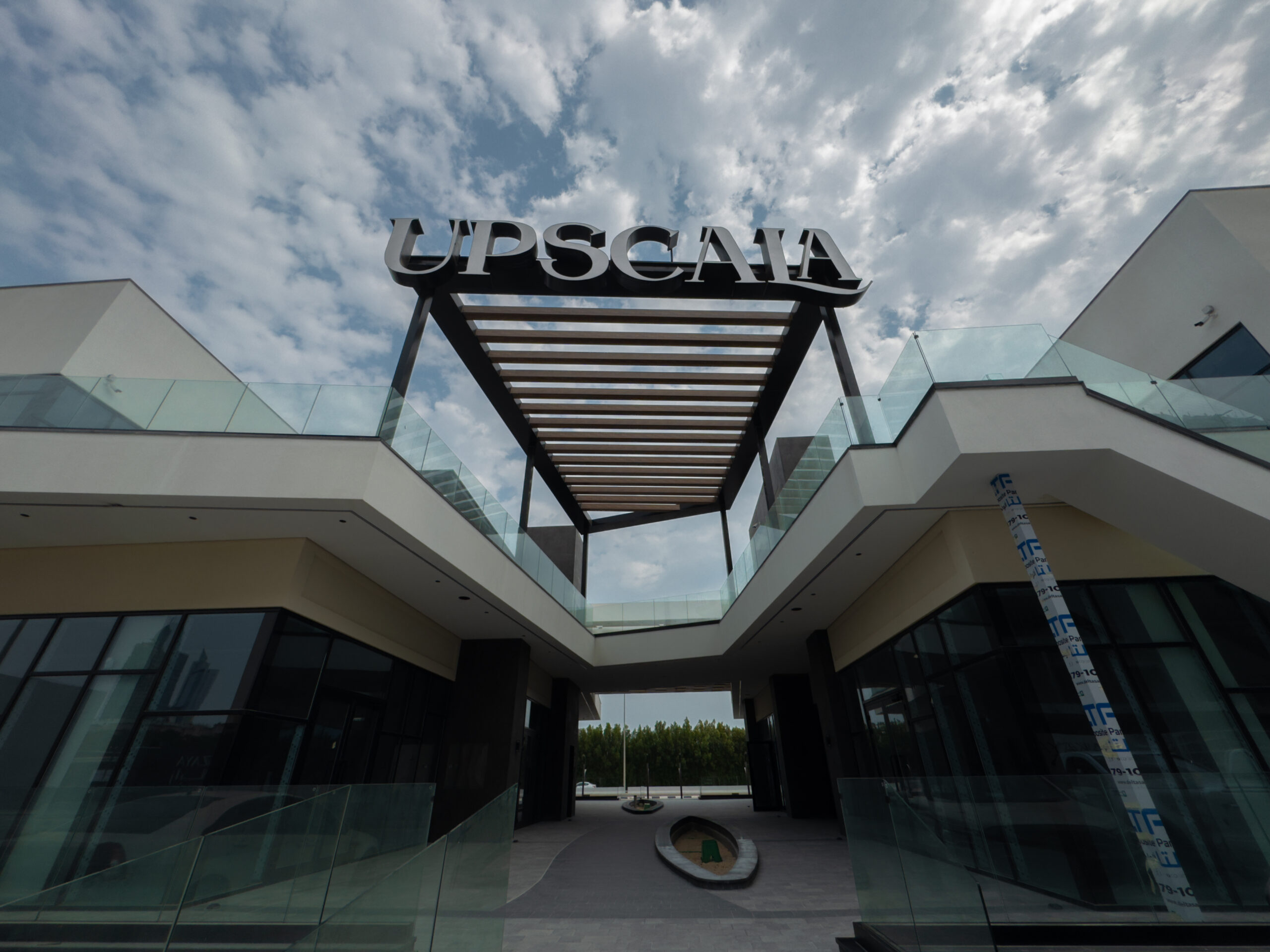
Upscala — Premium F&B Commercial Development, Al Khobar
03 / Selected Project • Handed Over to RIKAZ

Premium Restaurants & Cafés • Al Khobar, KSA

UPSCALA

Role: Consultant Project Manager

High-end commercial destination featuring two-level retail & F&B units, outdoor terraces, steel & timber-louvered shade structures, glazed façades, and pedestrian circulation.

2,255 m²
Land Area
8 Units
Premium F&B
100%
Handover Review

Supervision Scope: Architectural review, weekly progress reporting, municipality observations, snagging, and payment administration.

Documented Record: Named "Consultant Project Manager" in supervision reports through completion review and handover follow-up.

02  /  Behance Featured Work & Exterior Visualizations

Architecture, Landscape & Façades

View Full Behance Portfolio ↗
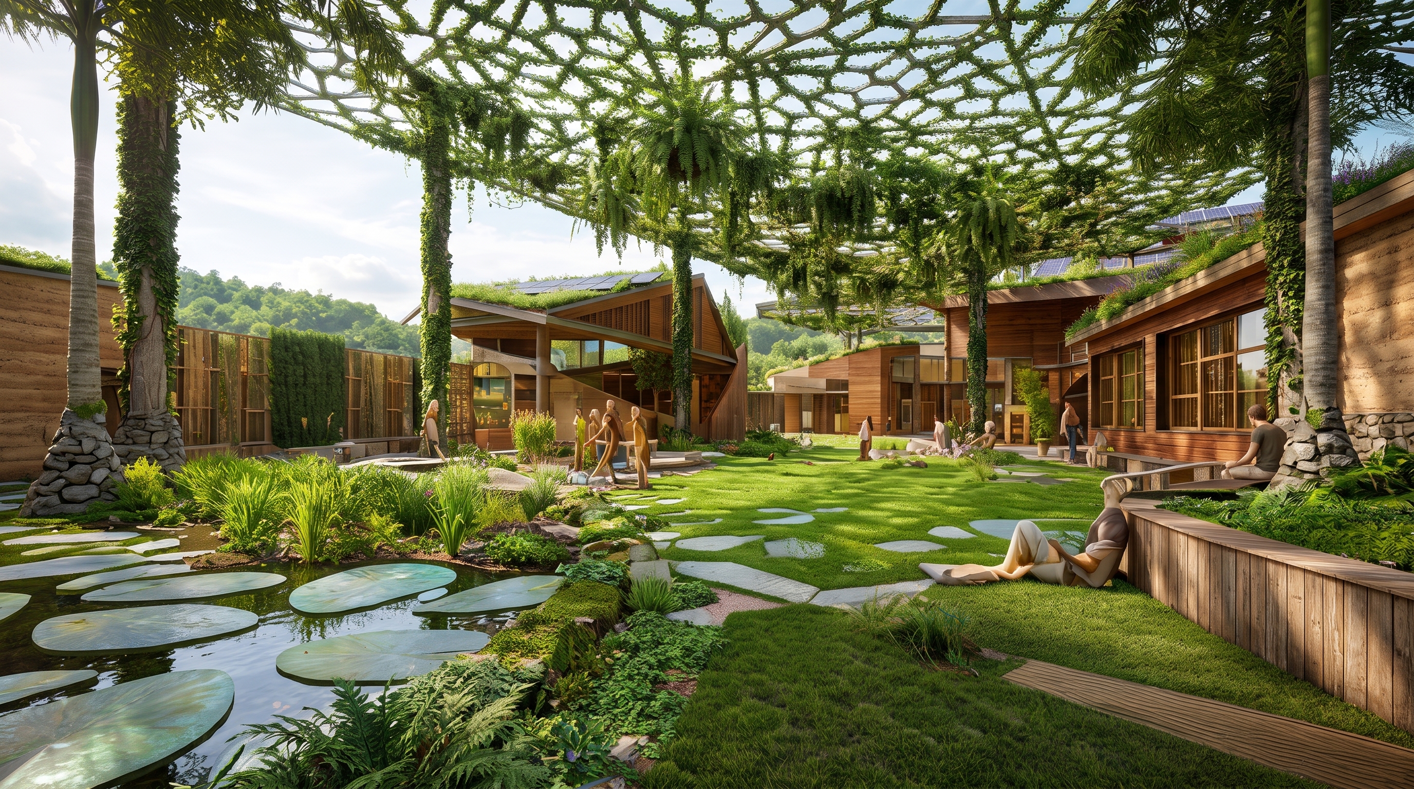
Cultural Hub for Desertification Awareness (2023)
Environmental Architecture • 2023
Parametric Canopy & Ecological Center

Cultural Hub for Desertification Awareness

Climate-responsive cultural complex featuring a sprawling biomimetic Voronoi shade canopy supported by structural funnel columns, cellular courtyard paving, native xeriscaping, and low-energy exhibition pavilions.

Concept • 3D Visualization Behance Case Study ↗
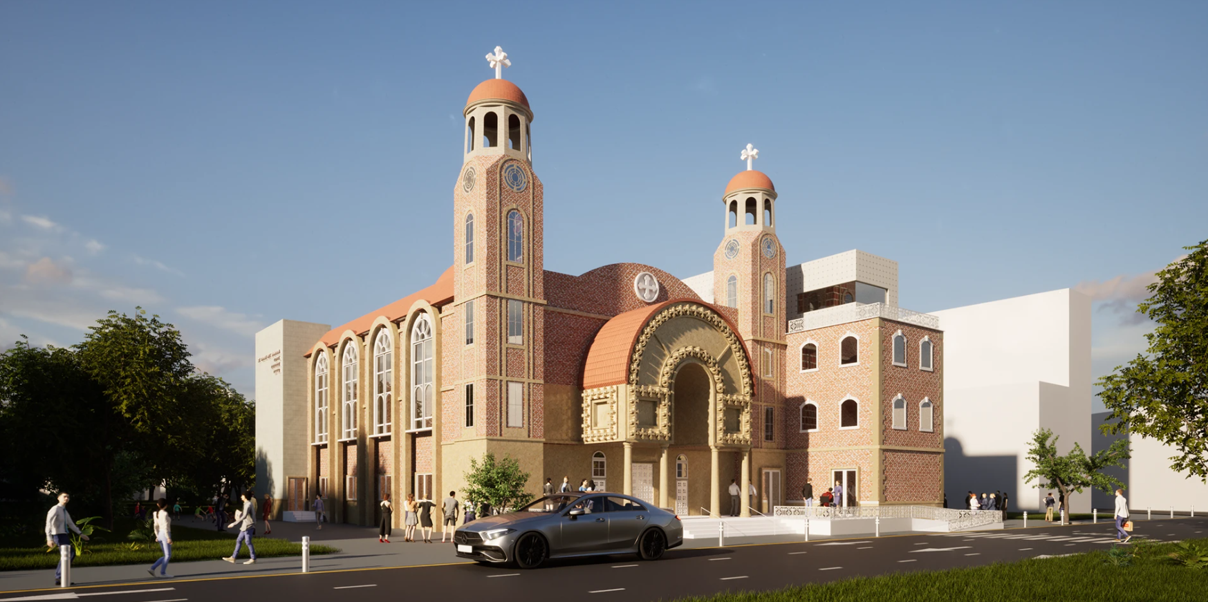
St. George and St. Shenouda Coptic Orthodox Church (2023)
Sacred Architecture • 2023
Heritage & Monumental Design

St. George & St. Shenouda Coptic Orthodox Church

Monumental Coptic ecclesiastical architecture defined by twin domed bell towers, an intricately carved barrel-vaulted entrance portico supported by classical columns, rhythmic arched side bays, and an integrated community wing.

Architecture • Modeling Behance Case Study ↗
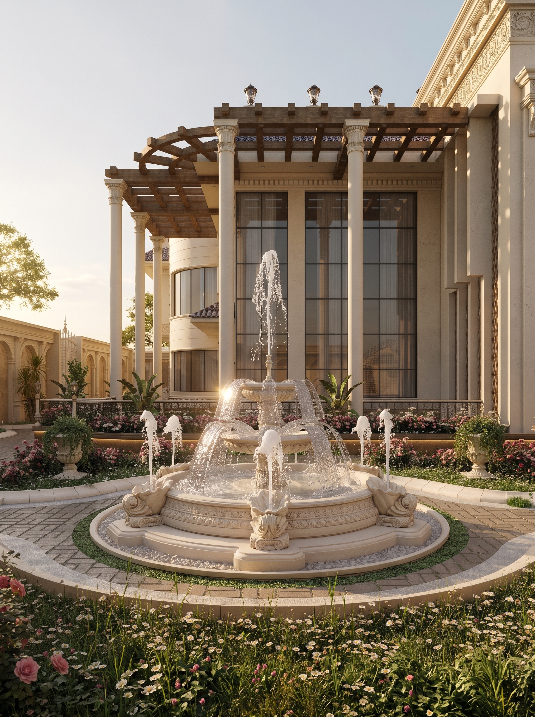
Villa Al Malqa Landscape — Riyadh (2023)
Landscape Design • 2023
Riyadh, Saudi Arabia

Villa Al Malqa Landscape

Private luxury residence courtyard and landscape design featuring a monumental double-height Corinthian colonnade, radial overhead trellis pergola, classical tiered marble water fountain, and curated garden planting.

Landscape • Exterior Behance Case Study ↗
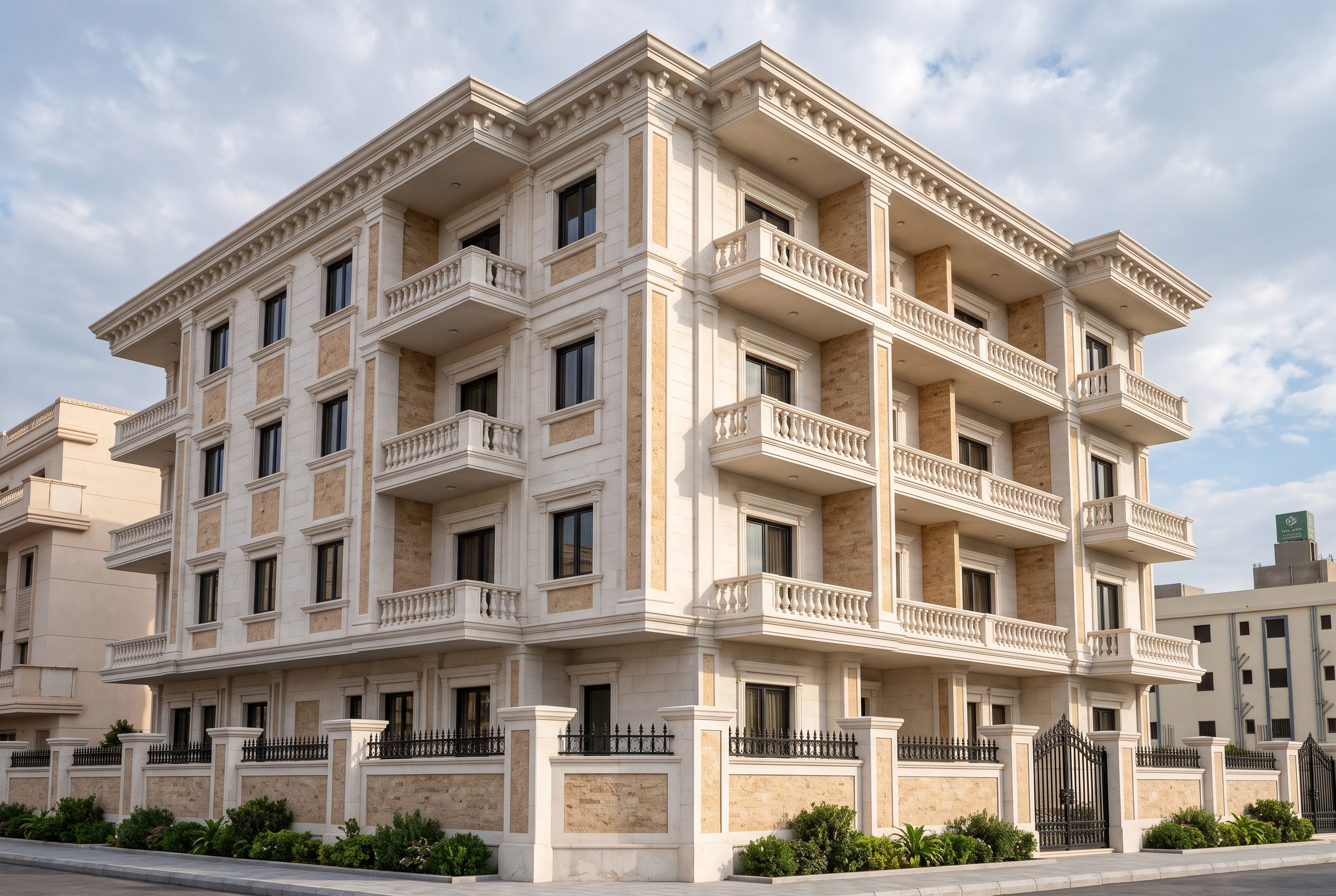
Building 1 — Neoclassical Limestone Residence (25.88m × 17.88m)
Building 1 • Exterior Façade
25.88 m × 17.88 m Footprint • Sheets A-201–A-204

Neoclassical Limestone Residence (Building 1)

Four-story classical residential elevation featuring ST-01 main white limestone, ST-02 warm beige stone inlay, dentil cornice crowning, turned vase balustrades, and an illuminated perimeter wall.

3D Render • Full CAD Package View 2D CAD Sheets ↓
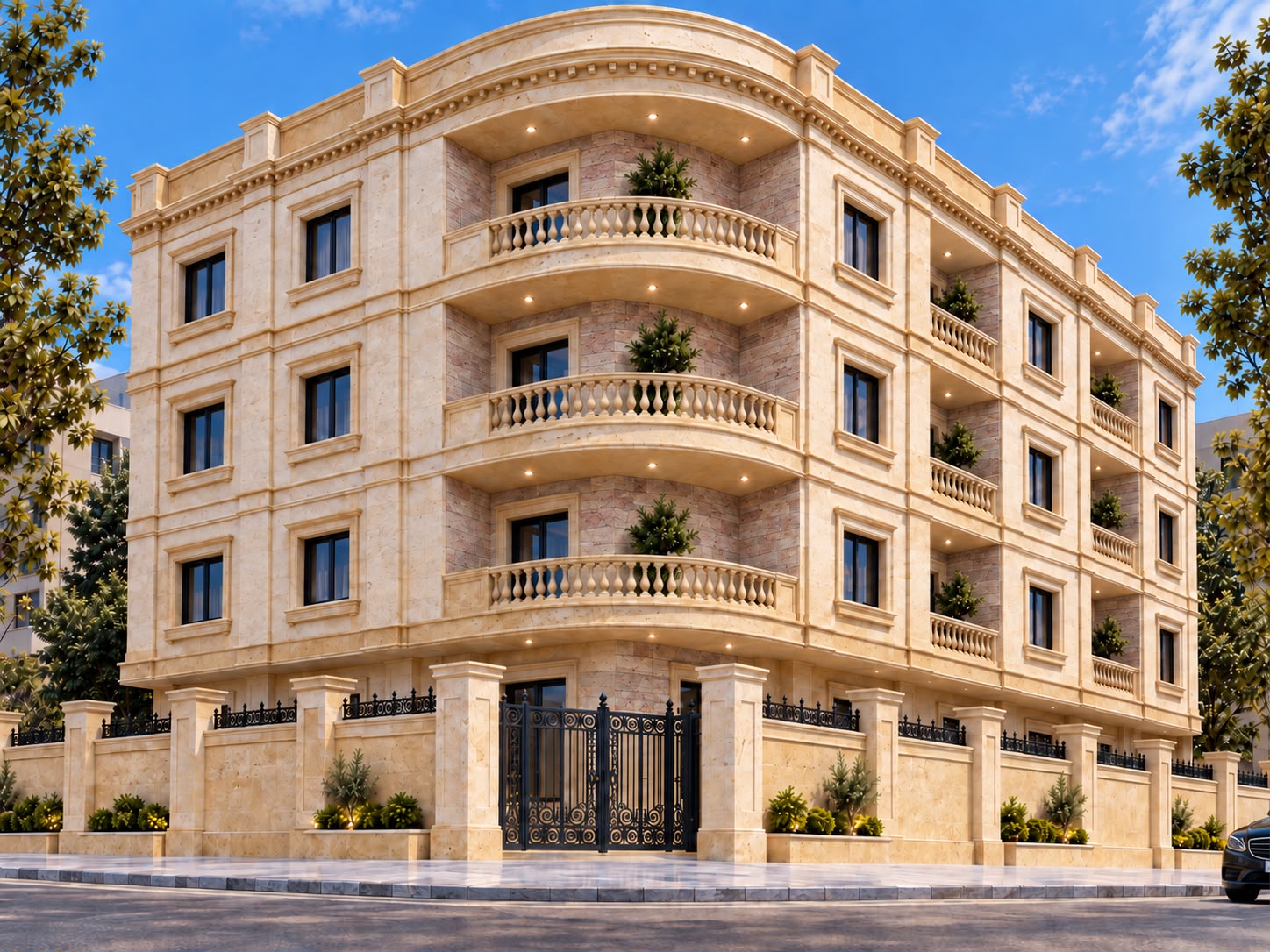
Building 2 — Curved-Corner Classical Palazzo (26.86m × 15.10m)
Building 2 • Corner Elevation
26.86 m × 15.10 m Footprint • Sheets B-201–B-204

Curved-Corner Classical Palazzo (Building 2)

Monumental curved S.E. corner façade (8.09 m balustrade arc, 8.44 m cornice arc) anchoring a four-level luxury residential building with radial CNC stone templates and classical pilasters.

3D Render • Radial CNC CAD View 2D CAD Sheets ↓

03  /  Material • Light • Detail

Selected Interior Visualizations

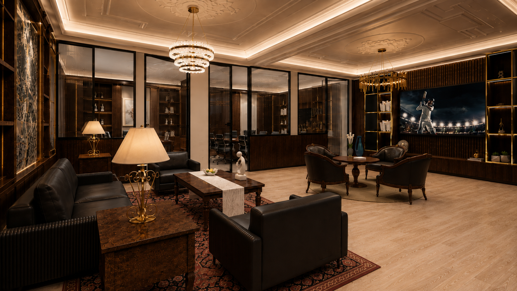
Spatial experience and bespoke classical-modern corporate interiors, crafted with rich walnut paneling, coffered lighting geometry, and refined material palettes.

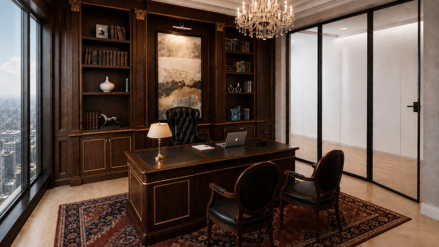
Executive Suite & Library — Interior Visualization 01 / Selected View

Executive Suite & Library

Bespoke Joinery

Classical dark-wood millwork with gold-leaf Corinthian capitals, crystal chandelier focal point, and contemporary glass partition integration.

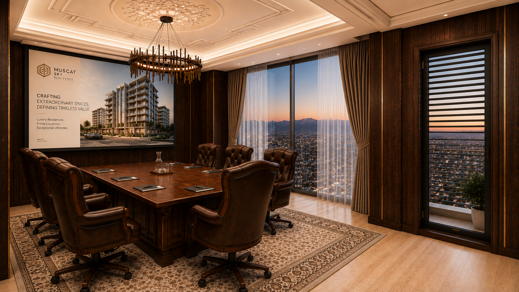
Skyline Executive Boardroom — Interior Visualization 02 / Spatial Experience

Skyline Executive Boardroom

Lighting & Acoustics

Double-cove illuminated gypsum ceiling with ornate plaster medallions, tufted leather seating, and floor-to-ceiling panoramic city views.

Private Client Lounge — Interior Visualization 03 / Material & Light

Private Client Lounge

Interior Visualization

Herringbone parquet flooring, fluted timber feature walls, warm ambient lamp lighting, and glazed acoustic dividers into adjacent meeting zones.

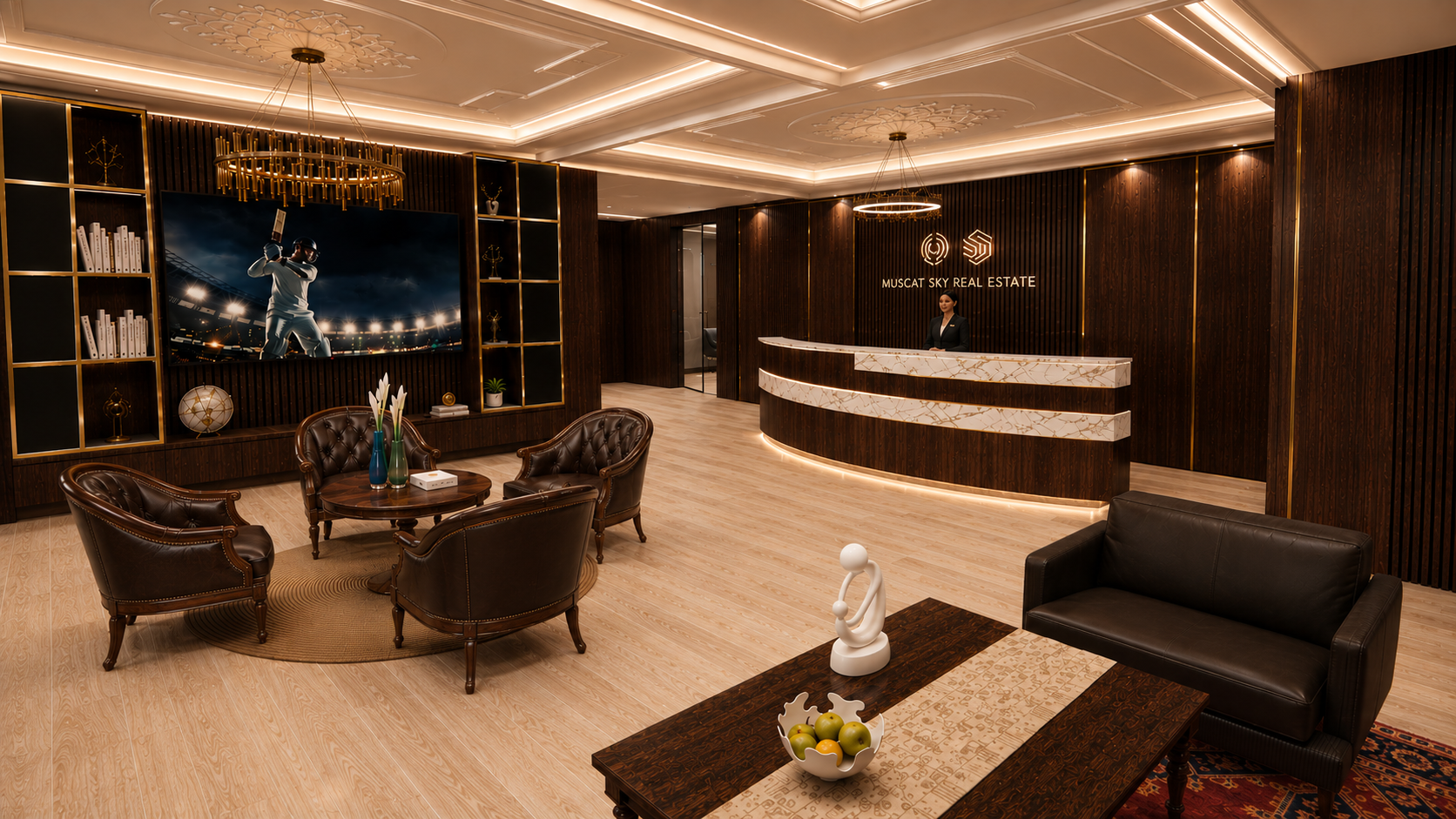
Muscat Sky Real Estate HQ — Commercial Lobby 04 / Concept & Detail

Muscat Sky Real Estate HQ

Commercial Lobby

Curved marble-and-walnut reception desk with integrated LED strips, branded slat-wall backdrop, and executive waiting lounge.

04  /  Technical Execution • Orthographic Elevations & 1:20 Sections

Design Creation

Master 2D AutoCAD Working Drawing Package — Buildings 1 & 2 (All 8 Elevations & 1:20 Details)

8 Working Drawing Sheets • 1:100 & 1:20 Scale
ST-01
Main White / Cream Natural Limestone

Ashlar coursing, classical fluted pilasters, stepped dentil cornice & drip overhang (+600 mm / +520 mm).

ST-02
Warm Beige / Golden Molded Stone Inlay

Recessed spandrel panels (-20 mm), window casings (+80 mm), and turned vase balusters (H = 920 mm).

ST-03
Terrace Wall Honed / Veined Stone Tiles

Inner loggia & curved balcony backing walls with mechanical stainless-steel corbel anchors & epoxy pins.

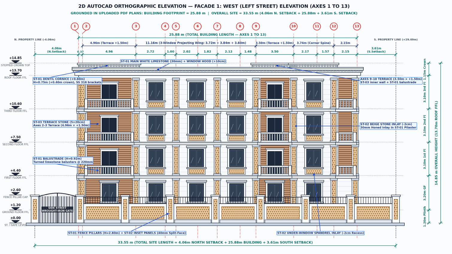
Sheet A-201 — Building 1 West (Left Street) 2D Working Elevation (Axes 1–13, 25.88 m / 33.55 m) Sheet 1 of 8 • A-201

1. Building 1 — Sheet A-201: West (Left Street) Elevation

Axes 1 to 13

Full working elevation across structural axes 1 to 13 (25.88 m building footprint plus 4.06 m North and 3.61 m South setbacks = 33.55 m site length), showing Axes 2–3 (4.96 m × +1.50 m) and Axes 9–10 (3.50 m × +1.50 m) cantilevered terraces, Axes 3–9 (11.16 m) three-window central wing, Axes 10–12 (3.74 m) corner spine, ashlar coursing, turned vase balusters, and full ST-01 / ST-02 / ST-03 material legend.

Footprint: 25.88 m • Site: 33.55 m Click Drawing to Enlarge
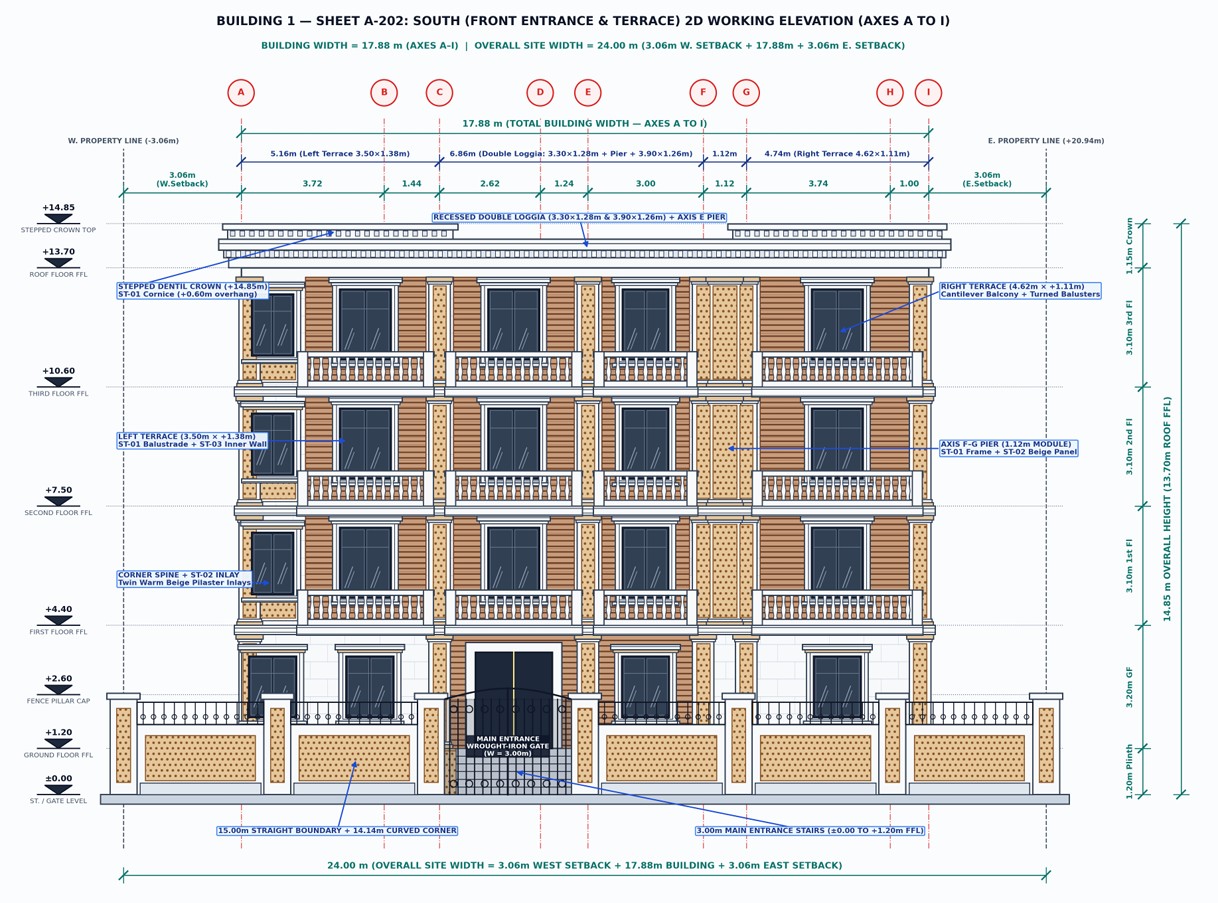
Sheet A-202 — Building 1 South (Front Main Entrance & Terrace) 2D Working Elevation (Axes A–I, 17.88 m / 24.00 m) Sheet 2 of 8 • A-202

2. Building 1 — Sheet A-202: South (Front Entrance) Elevation

Axes A to I

Full working elevation across horizontal bays A to I (17.88 m building footprint plus 3.06 m West and 3.06 m East setbacks = 24.00 m site width), detailing the Left Corner Terrace (3.50 m × +1.38 m), the Center Double-Bay Recessed Loggia (3.30 m × 1.28 m and 3.90 m × 1.26 m above the 3.00 m main entrance stairs and arched wrought-iron gate), and the Right Corner Terrace (4.62 m × +1.11 m).

Width: 17.88 m • Site: 24.00 m Click Drawing to Enlarge
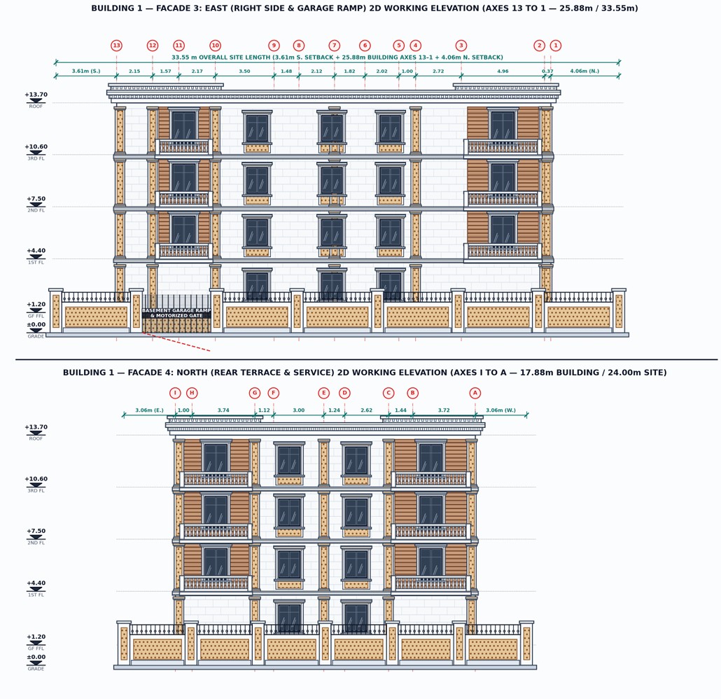
Sheet A-203 — Building 1 East (Axes 13–1, 25.88 m) and North Rear (Axes I–A, 17.88 m) 2D Working Elevations Sheet 3 of 8 • A-203

3. Building 1 — Sheet A-203: East & North Rear Elevations

Axes 13–1 & I–A

Complete working elevations for Building 1’s remaining two façades: the East Elevation (Axes 13 to 1, 25.88 m / 33.55 m) including the 5.17 m basement garage ramp, S.E. corner terrace (4.62 m), and N.E. terrace (5.32 m); and the North Rear Elevation (Axes I to A, 17.88 m / 24.00 m) including the 4.06 m North setback, N.E. & N.W. corner terraces (5.21 m × 1.50 m), and central service/staircase window bays.

Dual Orthographic Sheet • 1:100 Click Drawing to Enlarge
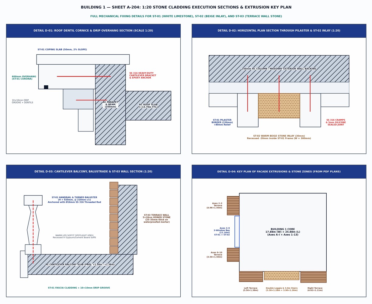
Sheet A-204 — Building 1 1:20 Mechanical Stone Fixing Details (D-01 to D-03) and Floor Plan Extrusion Key (D-04) Sheet 4 of 8 • A-204 (1:20)

4. Building 1 — Sheet A-204: 1:20 Cladding Sections & Key Plan

Details D-01–D-04

1:20 construction sections for Building 1 detailing the Roof Dentil Cornice & Drip Overhang (Detail D-01, +600 mm), the Horizontal Plan Section Through Pilaster & ST-02 Warm Beige Inlay (Detail D-02, +80 mm / -20 mm), the Cantilever Balcony, Turned Vase Balustrade & ST-03 Veined Wall Section (Detail D-03, H = 920 mm), and the Floor Extrusion & Stone Zone Key Plan (Detail D-04).

1:20 Mechanical Fixing Details Click Drawing to Enlarge
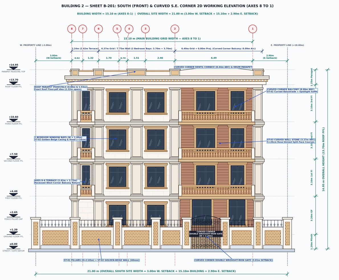
Sheet B-201 — Building 2 South (Front) & Panoramic Curved S.E. Corner 2D Working Elevation (Axes 8–1, 15.10 m / 21.00 m) Sheet 5 of 8 • B-201

5. Building 2 — Sheet B-201: South & Curved S.E. Corner

Axes 8 to 1

Full working elevation for Building 2 across horizontal axes 8 to 1 (15.10 m building width plus 3.00 m West and 2.90 m East setbacks = 21.00 m South site width), showing the Axes 8–6 S.W. Terrace (2.42 m × 2.72 m), the Axes 6–2 Two-Bedroom Wing (two 1.40 m windows and 0.80 m / 1.53 m rooftop parapet pedestals), and the Axes 2–1 Panoramic Curved Corner Balcony (8.09 m balustrade arc, 8.44 m cornice arc, 3.27 m ST-03 inner curved wall, and 3.20 m double wrought-iron corner gate).

Curved Arc: 8.09 m • Width: 15.10 m Click Drawing to Enlarge
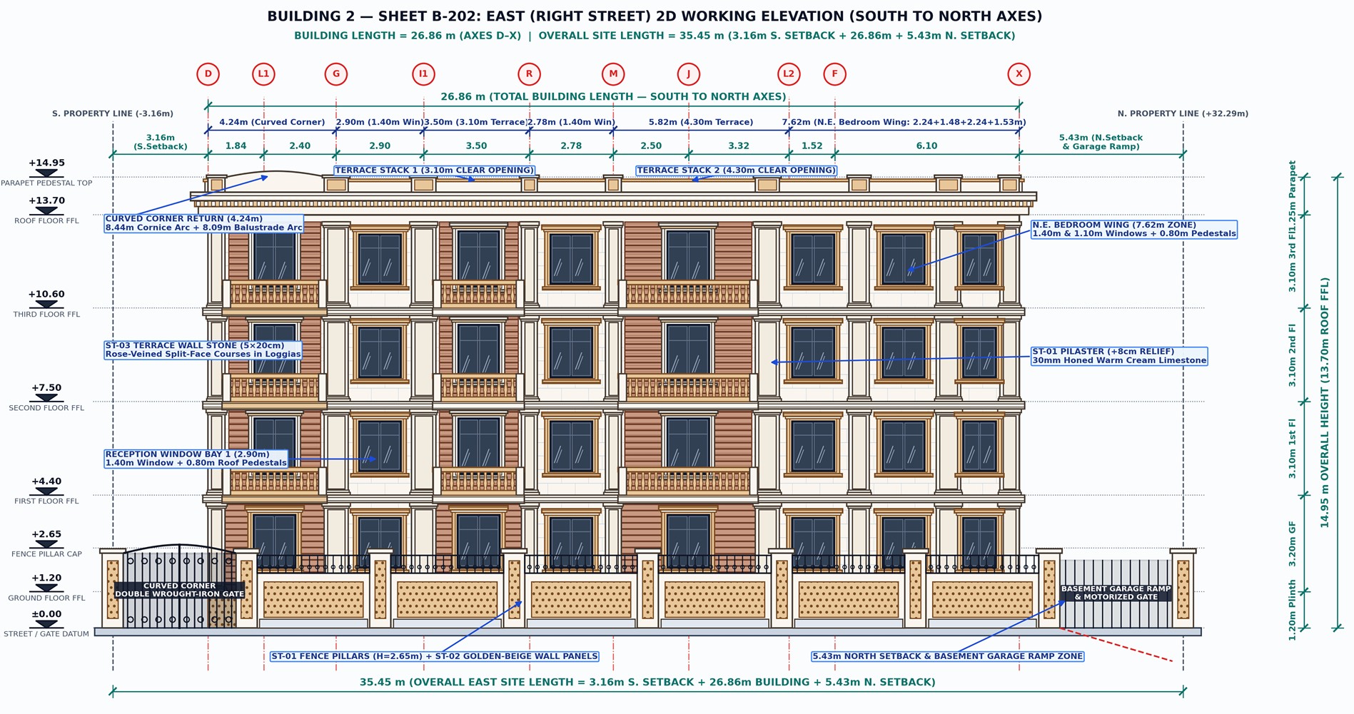
Sheet B-202 — Building 2 East (Right Street) 2D Working Elevation (Axes D–X, Building Length = 26.86 m, Site Length = 35.45 m) Sheet 6 of 8 • B-202

6. Building 2 — Sheet B-202: East (Right Street) Elevation

Axes D to X

Full working elevation along the East street frontage across all nine structural bays from South to North (26.86 m building length plus 3.16 m South and 5.43 m North setbacks = 35.45 m site length), detailing the Curved Corner Return (4.24 m), Reception Window Bay 1 (2.90 m), Recessed Terrace Stack 1 (3.10 m clear opening), Living/Reception Window Bay 2 (2.78 m), Recessed Terrace Stack 2 (4.30 m clear opening), and the North-East Bedroom Wing (7.62 m).

Length: 26.86 m • Site: 35.45 m Click Drawing to Enlarge
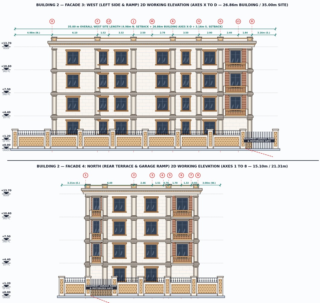
Sheet B-203 — Building 2 West Side (Axes X–D, 26.86 m) and North Rear (Axes 1–8, 15.10 m) 2D Working Elevations Sheet 7 of 8 • B-203

7. Building 2 — Sheet B-203: West & North Rear Elevations

Axes X–D & 1–8

Complete working elevations for Building 2’s remaining two façades: the West Side Elevation (Axes X to D, 26.86 m / 35.00 m) showing the 3.00 m West setback, S.W. basement ramp, Bedroom/M.B.Room 1.40 m windows, Kitchen/Bath windows, and 2.72 m S.W. terrace; and the North Rear Elevation (Axes 1 to 8, 15.10 m / 21.31 m) showing the 5.43 m / 4.98 m North garage ramp zone, N.E. terrace (2.25 m × 1.41 m), and N.W. terrace (3.60 m).

Dual Orthographic Sheet • 1:100 Click Drawing to Enlarge
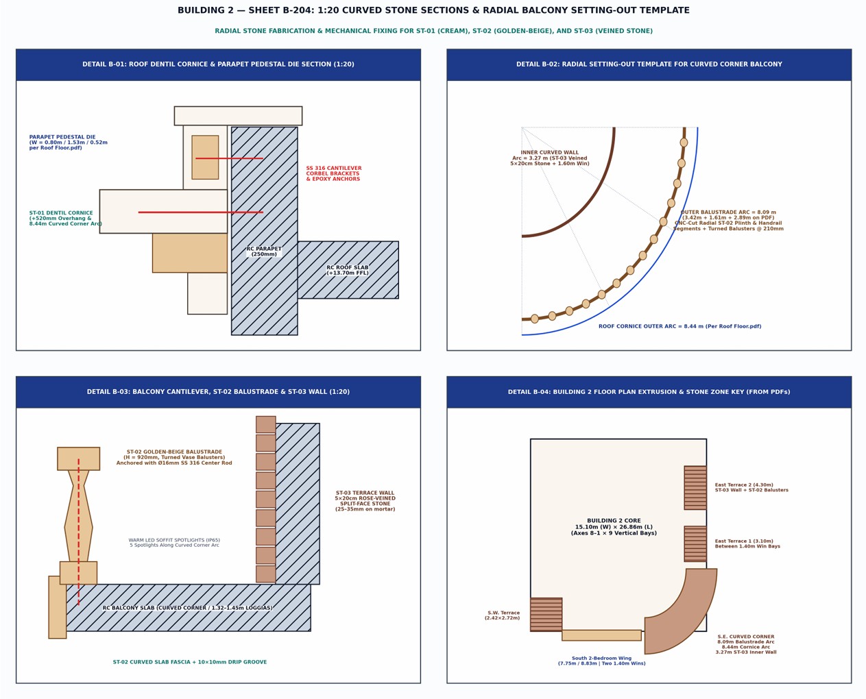
Sheet B-204 — Building 2 1:20 Radial & Section Details (B-01 to B-03) and Floor Plan Extrusion Key (B-04) Sheet 8 of 8 • B-204 (1:20)

8. Building 2 — Sheet B-204: 1:20 Radial CNC Template & Sections

Details B-01–B-04

1:20 construction details for Building 2 including the Roof Dentil Cornice & Parapet Pedestal Die Section (Detail B-01, +520 mm overhang & 0.80 m / 1.53 m pedestals), the Radial CNC Stone Setting-Out Template for the Curved Corner Balcony (Detail B-02, 3.27 m inner arc, 8.09 m balustrade arc, 8.44 m cornice arc), the Curved Turned Vase Balustrade & Spotlight Soffit Section (Detail B-03), and the Building 2 Extrusion & Stone Zone Key Plan (Detail B-04).

Radial CNC Template • 1:20 Details Click Drawing to Enlarge

05  /  Certified Record • Egypt (2019–2020)

National Mega-Projects & Infrastructure

Engineering Authority of the Armed Forces — Design Branch

Formally commended by the Military Engineers Administration (Design Branch) for high-level architectural design and structural drawing contributions across flagship national projects in Egypt.

Civic & Cultural

Al-Fattah Al-Aleem Mosque (VIP Halls)

Architectural & structural design packages, alongside Mosque of Egypt Cultural Center & EIEC Exhibition Center.

Urban & Public Realm

Mamsha Ahl Misr Walkway

Cairo Nile waterfront promenade & Galala Resort and City in Ain Sokhna.

Residential & Healthcare

New Mansoura & Aswan General Hospital

New Mansoura City housing, Sandoub City residential works, and Aswan General Hospital.

Aviation & Transport

Sharm El-Sheikh TMA & National Tunnels

Air Traffic Control Building (TMA), June 30 Tunnels, National Toll Gates, and Pedestrian Bridges.